30 KiB
Build Your First Graph-based Multi-Agent Workflow
The example above demonstrates a multi-agent workflow for content creation. This tutorial will walk you through how to use a Graph structure to organize multiple Agent nodes, completing a full process from content generation, editing, to human review. By following the steps below, you will build your first graph-based multi-agent workflow.
- 1. Create a Graph
- 2. Create Nodes
- 3. Transfer Information Between Nodes
- 4. Graph Startup and Execution Logic
- 5. Build Review and Revise Loop
- More Details
1. Create a Graph
What is a Graph?
A Graph is the execution carrier and scheduling structure for multi-agent systems. It describes the dependencies and execution order between nodes (Agents), essentially representing a complete workflow.
The Graph itself does not perform specific tasks, but is responsible for organizing, orchestrating, and scheduling the execution logic of each node.

What is a Variable?
A Variable provides configurable global or local parameters for the Graph. Once defined, nodes (Agents) can directly reference these variables, enabling parameter sharing and decoupling configuration.
It is recommended to manage common or sensitive configurations such as API Keys globally here.
Note that if the required environment variables are already defined in the outer .env file and you intend to use them directly, there is no need to configure them here again.
If the variables are configured here, these settings will take precedence over those defined in the outer .env file.

2. Create Nodes
What is a Node?
A Node is the smallest execution unit in a Graph, usually corresponding to an Agent. Each node should have relatively independent capabilities and clear responsibilities.
Creating Agent Nodes
In this example Graph, we create the following three nodes:
- Poet: Responsible for generating poetry or creative content
- Article Writer: Responsible for generating structured articles
- Editor 1: Responsible for initial editing and content integration
All of the above are Agent Nodes. Below, we use the Poet node as an example to show the complete process of creating an Agent node.
Prompts (Copy to Configure)
Use the following prompts as the role field for each Agent node.
Poet
You are a poet who crafts a modern English poem based on a single word or short phrase.
The user will input a word or short phrase. Write a modern English poem inspired by it.
Article Writer
You are a writer who excels at generating a full article from a single word or short phrase.
The user will input a word or short phrase, and you must produce an article of at least 2000 words with multiple paragraphs.
Editor 1
You are an editor. Combine the article and the poem, and append the poem at the end of the article.

3. Transfer Information Between Nodes
What is a Message?
Message is the basic unit of information transmission and storage, the basic unit of context control, as well as the basic unit of edge processing and control.
- It can transmit text and multimodal information.
- The input and output of a node can be multiple messages.
- The user's initial input is a single message.
- When Dynamic Execution Mode (which can be ignored for now) is not configured on the edge, the output of other node types except the Passthrough Node and Subgraph Node (when it ends with a Passthrough Node) is a single message. All configurations in this tutorial result in a single Message output.
What is an Edge?
An Edge connects nodes, and its core functions include:
- Information Transfer: Passing the output of upstream nodes as input to downstream nodes
- Execution Control: Defining execution dependencies and trigger relationships between nodes
Note
: If the upstream node outputs multiple messages, the edge will evaluate, process, and transmit each message individually.
Establishing Node Connections
Based on the three nodes created, establish the following connections:
Poet → Editor 1Article Writer → Editor 1
At this point, the Graph forms a typical "parallel generation → summary editing" structure.

4. Graph Startup and Execution Logic
Entry Nodes
When the Graph starts:
- All Nodes connected to the start node are treated as workflow Entry Nodes
- These nodes receive user input simultaneously at startup and execute in parallel
- A workflow can have multiple Entry Nodes; simply create edges connected to the start node via drag-and-drop
Therefore, in the current setup, Poet and Article Writer will run in parallel, as shown below.

At this point, you have built a minimal multi-agent workflow.
5. Build Review and Revise Loop
Creating a Second Editing Node
Next, we create a new Agent node Editor 2, which is responsible for revising and polishing the content based on human feedback.
Then establish the following connection:
Editor 1 → Editor 2(trigger = false)

In this configuration, an important edge attribute is involved: trigger
triggercontrols whether the target node is executed- When the edge is active and
trigger = true, the target node is marked to trigger and will execute once the execution layer reaches that node's layer
Editor 2 Prompt (Copy to Configure)
You are an editor skilled at integrating and polishing an article.
Based on the article and the revision suggestions, refine and revise the article. Output only the revised article.
Set the Context Window
To give the Agent contextual memory, set this on Editor 2:
Context Window Size = 7
This keeps the newest 7 messages (including node input and output messages).
What is a Context Window?
In DevAll, the context window is a node-level retention policy. After each run, the node tries to clean up its own input queue of Messages, keeping only what satisfies the retention rules to control context size. This does not affect the current run; it only affects inputs visible in later runs.
Rules (configured via Context Window Size on the node):
0: clear all context, keeping only messages marked byKeep Message Input = Trueon edges.-1: keep all messages.> 0: keep the newest N messages (kept messages still count toward the limit).- When
Context Window Size != 0, the system automatically saves the node's output messages into that node's context for later runs.
Tips:
- For long-lived context, use
Keep Message Inputin Edge config or the Memory module.
Human Node: Introducing Human-in-the-Loop
Human Node is a special type of node that introduces human participation into the execution flow of the Graph. It does not generate content itself; instead, it serves as a flow control node, receiving and processing human input and feedback to influence subsequent execution paths.
Common use cases include:
- Content review: manual inspection and approval of generated results
- Decision and confirmation: introducing human decisions at critical steps
- Execution path control: determining workflow branching based on human feedback

Human Node Instruction (Copy to Configure)
Use the following text as the description for the Human node.
Please provide revision suggestions for the article, or enter ACCEPT to exit the loop.
In this example, we want to determine whether a second editing step is required based on the input received by the Human Node:
- When the Human Node receives
ACCEPT, the result is considered approved and no further modification byeditor2is needed - Otherwise, the workflow proceeds to
editor2for additional revision
To implement this logic, we need to configure Conditional Edges between nodes.

In the configuration above, a key edge attribute is used: condition, which controls whether the edge is active:
- When
conditionevaluates totrue, the edge becomes active and the workflow can continue along this path - When
conditionisfalse, the edge is treated as disconnected and has no effect on the
With these steps, we have added a more complex review-and-revision workflow. The execution flow is shown below.

Below are more detailed informations about this system:
More Things
We provide a set of examples: files named demo_*.yaml are feature/module demos, while files named directly (e.g., ChatDev_v1.yaml) are in-house implementations or recreated workflows.
- Node Types Explained
- Edge Configuration
- Graph Execution Logic
- Workspace Structure
- Dynamic Execution Mode
Node Types Explained
DevAll provides various node types, each with specific purposes and configuration options.
Agent Node
Agent Nodes are the core node type, used to call large language models (LLMs) for text generation, dialogue, reasoning, etc. They support multiple model providers (OpenAI, Gemini, etc.) and can be configured for tool calling, memory, and other advanced features.
Basic Configuration Example

Tooling
Agent Nodes can be configured with tools, allowing the model to call external APIs or execute functions. Click Advanced Settings to see the options. Multiple tools can be configured, such as both MCP and Function tools, or multiple MCP tools.

DevAll supports two types of tools:
1. Function Tooling (Local Functions)
Call Python functions in the repository (under functions/function_calling/):

uv_related:All in the figure means importing all functions from functions/function_calling/uv_related.py. Others import specific functions.
To add a custom function, create a Python file under functions/function_calling/ and use type annotations for parameters:
from typing import Annotated
from utils.function_catalog import ParamMeta

def my_tool(
    param1: Annotated[str, ParamMeta(description="Parameter description")],
    *,
    _context: dict | None = None,  # Optional, for accessing context. The system injects this automatically and does not expose it to the model. See functions/function_calling/file.py for usage.
) -> str:
    """Function description (will be shown to LLM)"""
    # The return value can be any type; the system will convert it to a string for the model.
    # If the return value is MessageBlock or List[MessageBlock], multimodal information can be passed to the model (see load_file in functions/function_calling/file.py)
    return "result"
After adding, restart the backend server to use the function in Agent Nodes.
Built-in Tools Quick Reference
The system includes several built-in tools that can be used directly in Agent Nodes:
| Module | Key Functions | Description | Example |
|---|---|---|---|
| file.py | save_file, load_file, list_directory, search_in_files, etc. |
File operations | ChatDev_v1 |
| uv_related.py | install_python_packages, init_python_env, uv_run |
Python environment management | ChatDev_v1 |
| deep_research.py | search_save_result, report_* series |
Deep research & report generation | deep_research_v1 |
| web.py | web_search, read_webpage_content |
Web search & content retrieval | deep_research_v1 |
| video.py | render_manim, concat_videos |
Manim video rendering | teach_video |
| code_executor.py | execute_code |
Code execution | - |
| user.py | call_user |
User interaction | - |
For complete tool documentation, see
docs/user_guide/en/modules/tooling/function_catalog.md
2. MCP Tooling (External Services)
Connect to external services that comply with the Model Context Protocol:
Remote mode (connect to a deployed HTTP service):
 The Authorization header in the image is optional and can be filled as needed.
Local mode (start a local process):

Memory Module
The Memory module allows Agents to retrieve and store information, supporting read/write control.
Configuration Steps
- Declare a Memory Store at the Graph level:

Hover over the three bars in the lower right corner of the Workflow page, click Manage Memories, and add a new Memory Store. Here we add a SimpleMemory Store named Paper Gen Memory for storing conversation memory.

SimpleMemory requires Embedding configuration. Click Embedding Configuration, select an Embedding Provider (currently only openai is supported, users can extend it), and specify a model (e.g., text-embedding-3-small).

There are three built-in Memory types:
| Type | Features | Use Case | Needs Embedding | Example Config |
|---|---|---|---|---|
simple |
Vector search + semantic rerank | Conversation mem | Yes | yaml_instance/demo_simple_memory.yaml |
file |
File/directory vector index, RO | Knowledge base | Yes | yaml_instance/demo_file_memory.yaml |
blackboard |
Simple log, time/length cutoff | Broadcast board | No | yaml_instance/subgraphs/reflexion_loop.yaml |
- Reference in Agent Nodes: Click Memory Attachments, select the Memory Store, and configure read/write permissions and retrieval stages.

Top K controls the number of results per retrieval; Read/Write controls whether the node can read/write the Memory; Retrieve Stage controls at which execution stages to retrieve (can select multiple, others are for Thinking stage, currently unused; here we only select Gen Stage).

Human Node
Human Nodes introduce human interaction into the workflow. When executed, the workflow pauses and waits for user input.

Typical uses:
- Content review and confirmation
- Collecting suggestions
- Key decision points
- Data supplementation
Python Node
Python Nodes execute Python scripts. Scripts run in the code_workspace/ directory. Generally used to execute code generated by Agents; to run custom code, add a Literal node to output code and connect it to a Python node.
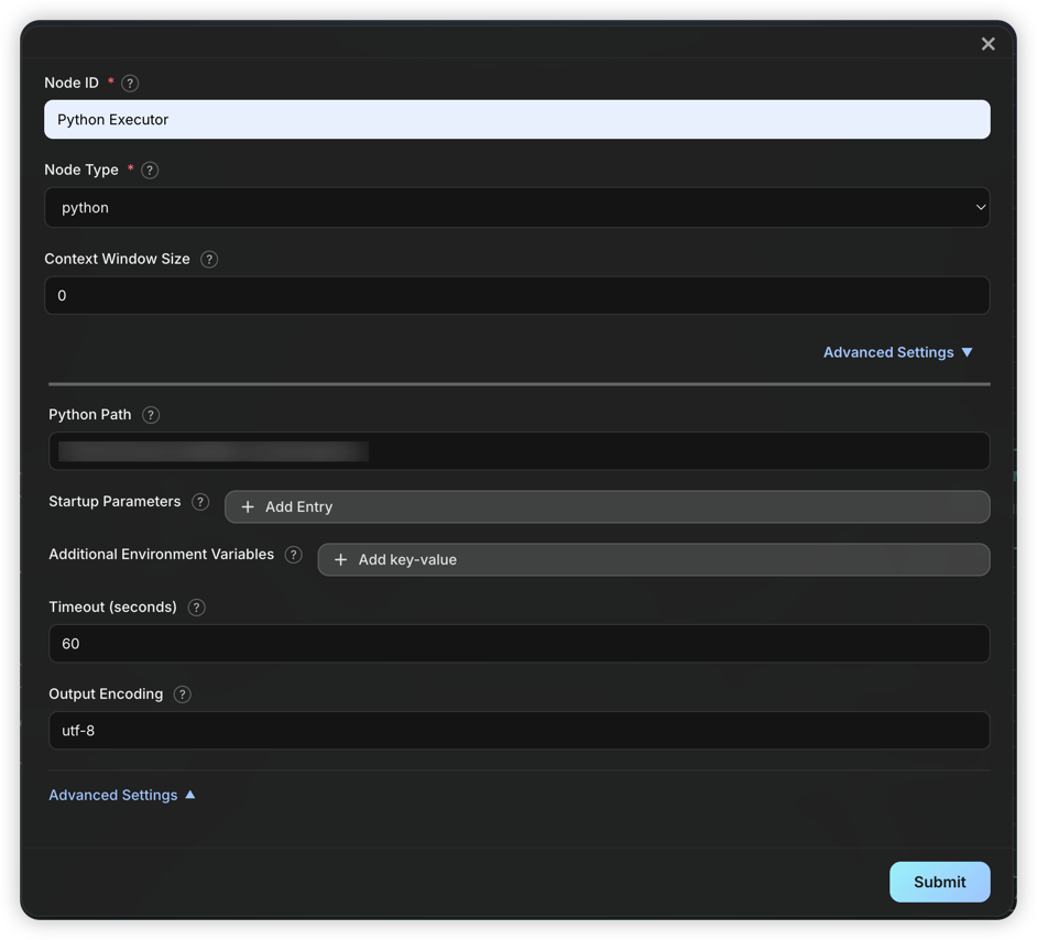
Execution mechanism:
- The node automatically extracts
python ...content from input; if extraction fails, the entire input is treated as the script. - Script stdout is passed as a Message to downstream nodes.
- You can specify environment variables, startup parameters, and timeout. Python Path usually does not need to be changed unless a specific Python version or venv is required.
- All Python nodes share the
code_workspace/directory, and user-uploaded files are saved in subdirectories for script access.
Passthrough Node
Passthrough Nodes do nothing but pass messages downstream. By default, only the last message is passed; you can change the config (Only Last Message) to pass all messages.

Key uses:
- Retain initial context as entry node: Use with
Keep Message Inputon edges to ensure the original task is always preserved (e.g.,yaml_instance/ChatDev_v1.yaml) - Filter redundant outputs in loops: Pass only the final result to control loop output and avoid context bloat
- Simplify graph structure: As a logical placeholder for organization and readability (e.g.,
yaml_instance/ChatDev_v1.yaml)
Literal Node
Literal Nodes output fixed text, ignoring all input. You can set the Message Role as user or assistant.

Typical uses:
- Inject fixed instructions or context (e.g.,
yaml_instance/ChatDev_v1.yaml) - Test downstream nodes (e.g.,
yaml_instance/demo_dynamic.yaml) - Fixed responses in conditional branches
Loop Counter Node
Loop Counter Nodes limit the number of loop executions. It counts triggers and only outputs when the limit is reached, terminating the loop.

How it works:
- Each trigger increments the counter by 1
- Counter <
max_iterations: No output, edge not triggered - Counter =
max_iterations: Output is produced, edge is triggered
Important
: Since no output is produced before the limit, the Loop Counter's edge must connect both to nodes inside the loop (to keep the loop going, but has no effect) and outside (to exit when the limit is reached).
See: yaml_instance/ChatDev_v1.yaml
Subgraph Node
Subgraph Nodes allow embedding another workflow graph into the current workflow for reuse and modular design. Subgraphs can come from external YAML files or be defined inline.
Key Configurations
| Field | Type | Description |
|---|---|---|
Subgraph Source Type |
string | Source type: file (external) or config (inline) |
Config |
object | Depends on Subgraph Source Type (see below) |
file type config:
| Field | Type | Required | Description |
|---|---|---|---|
Subgraph File Path |
string | Yes | Subgraph file path (relative to yaml_instance/ or absolute) |
config type config (inline definition):
Config items are the same as a normal graph.
Typical Uses
- Workflow reuse: Multiple workflows share the same sub-process (e.g., "article polishing" module)
- Modular design: Break complex flows into manageable units
- Team collaboration: Different teams maintain different subgraph modules
Note
:
- Subgraphs inherit the parent graph's
varsvariable definitions- Subgraphs execute as independent units with their own node namespace
startandendnodes determine data flow in/out:
start: Only needed if the subgraph is a loop.end: List of exit nodes. The system checks these in order and returns the first with output as the subgraph result. If none, or not set, nodes with no successors are used as exits.
See: yaml_instance/MACNet_optimize_sub.yaml, yaml_instance/MACNet_Node_sub.yaml, yaml_instance/MACNet_v1.yaml.
Edge Configuration
Edges connect nodes, controlling flow and data. Each node can have multiple outputs, all of which are processed by all edges.
Key Configurations
In edge config, click Advanced Settings to expand options:
| Field | Default | Description |
|---|---|---|
Edge Condition |
- | Whether the edge is active; default is always on |
Can Trigger Successor |
true |
Whether to trigger the target node. If false, does not trigger |
Pass Data to Target |
true |
Whether to pass data to the target node. If false, no data |
Keep Message Input |
false |
Whether to mark messages as kept (not auto-cleared) |
Clear Context |
false |
Whether to clear all non-kept history in the target node |
Clear Kept Context |
false |
Whether to clear all kept history in the target node |
Payload Processor |
- | Processor for message content |
Dynamic Expansion |
- | Dynamic execution config, see Dynamic Execution Mode |
Edge Condition
The condition determines whether the edge is on. If true, the edge is on (data can flow, can trigger); otherwise, it is off (no effect on downstream nodes).
Keyword Conditions (Common)

Function Conditions
Some built-in functions: true (default, always on), code_pass (code succeeded), code_fail (code failed), always_false (always off, for testing)
You can add custom functions in functions/edge and restart the backend to use them.

Payload Processor
A Payload Processor transforms or processes message content before passing through the edge. Useful for extracting info, format conversion, or custom logic.
Built-in Processor Types
1. regex_extract
Use Python regex to extract content from messages:
| Config Item | Description |
|---|---|
Regex Pattern |
Regex pattern (required) |
Capture Group |
Capture group name or index |
Case Sensitive |
Case sensitive (default true) |
Multiline Flag |
Enable re.MULTILINE (false) |
Dotall Flag |
Enable re.DOTALL (false) |
Return Multiple Matches |
Return all matches (default first only) |
Output Template |
Output template, use {match} |
No Match Behavior |
pass, default, drop |
Default Value |
Used if No Match Behavior=default |
Example: Extract code (see yaml_instance/demo_edge_transform.yaml)

2. function
Call Python functions in functions/edge_processor/ for custom processing:
| Config Item | Description |
|---|---|
name |
Function name (required) |
Built-in functions:
uppercase_payload: Convert message to uppercasecode_save_and_run: Save code to workspace and runmain.py(seeyaml_instance/MACNet_optimize_sub.yaml)
Custom Processor Functions
Create a Python file in functions/edge_processor/ and define a function:
from typing import Dict, Any

def my_processor(data: str, _context: Dict[str, Any]) -> str:
    """Function description (shown in config UI)"""
    # data is the message text
    # _context contains execution context
    return processed_data
Restart the backend to use the new function.
Graph Execution Logic
DAG Execution
For acyclic workflow graphs, the engine uses standard topological sorting:
- Build predecessor/successor relationships
- Calculate in-degree for each node
- Nodes with in-degree 0 are executed first
- Nodes in the same layer can execute in parallel
Loop Graph Execution
For graphs with loops, the engine uses Tarjan's strongly connected components algorithm for loop detection and recursive execution for nested loops.
Loop Detection and Super Node Construction
The system applies Tarjan's algorithm to the entire graph, identifying all strongly connected components (SCCs) in a single pass (O(|N|+|E|)).
- SCC: Maximal set of nodes where every pair is mutually reachable
- Loop: SCCs with more than one node; single-node SCCs without self-loops are normal nodes
After detection, each multi-node loop is abstracted as a Super Node, building a super node dependency graph. Since loops are encapsulated, the super node graph is always a DAG, allowing topological sorting.
Recursive Loop Execution
For loop super nodes, the engine uses the following recursive strategy:
Step 1: Identify Initial Node
Analyze loop boundaries to identify the uniquely triggered entry node as the Initial Node:
- Must be triggered by an external predecessor via a satisfied edge
- If no node is triggered, skip loop execution
- If multiple nodes are triggered, report config error
Step 2: Build Scoped Subgraph
Within the loop, build a subgraph logically removing all incoming edges to the initial node. This breaks the outer loop boundary for nested detection.
Step 3: Nested Loop Detection
Apply Tarjan's algorithm to the subgraph to detect nested loops. Since the initial node's incoming edges are removed, only true inner loops are detected.
Step 4: Inner Topological Sort
- If nested loops are found: Abstract each as a super node, build the dependency graph, and sort
- If not: Topologically sort the subgraph directly
Step 5: Layered Execution
Execute each layer in order:
- Normal nodes: Check trigger state and execute; initial node is forced to execute in the first round
- Inner loop super nodes: Recursively apply above steps
Step 6: Exit Condition Check
After each round, check exit conditions:
- Exit edge triggered: If any node triggers an edge to outside the loop, exit
- Max iterations: If
max_iterations(default 100) is reached, force exit - Initial node not retriggered: If not retriggered by inner predecessors, loop ends naturally
If none are met, repeat from Step 2.
Recursive capability: This forms a complete recursive structure, allowing the system to handle arbitrarily deep nested loops.
Execution Flowchart

Workspace Structure
DevAll uses a layered workspace structure to manage files:
Directory Structure
| Path | Purpose |
|---|---|
WareHouse/ |
Root directory for all sessions |
WareHouse/<session>/ |
Runtime data for a session |
WareHouse/<session>/code_workspace/ |
Python node code execution dir |
WareHouse/<session>/code_workspace/attachments/ |
User-uploaded files |
WareHouse/<session>/execution_logs.json |
Execution logs (after run) |
WareHouse/<session>/node_outputs.yaml |
Node output records (after run) |
WareHouse/<session>/token_usage_<session>.json |
Token usage stats (after run) |
WareHouse/<session>/workflow_summary.yaml |
Workflow summary (after run) |
Dynamic Execution Mode
Dynamic execution mode allows defining parallel processing at the edge level, supporting Map (fan-out) and Tree (reduction) modes.
See yaml_instance/demo_dynamic.yaml, yaml_instance/MACNet_Node_sub.yaml for examples.
Mode Comparison
| Mode | Description | Output | Use Case |
|---|---|---|---|
| Map | Fan-out, parallel | List[Message] |
Batch, parallel |
| Tree | Reduction, merge | Single Message |
Summarization |
Example Config
Dynamic config is defined on edges, indicating that messages passed through this edge need dynamic processing:
Map Mode

Tree Mode
For summarization:


(?s).{1,2000}(?:\s|$) splits input into segments of 2000 characters.
See yaml_instance/demo_dynamic_tree.yaml.
Split Strategies
| Type | Description |
|---|---|
message |
Each message as a unit (default) |
regex |
Split text using regex |
json_path |
Extract array elements from JSON output |
Mixing Static and Dynamic Edges
When a target node has both dynamic and static incoming edges:
- Dynamic edge messages: Split and executed multiple times
- Static edge messages: Copied to each dynamic instance